Friday, February 27, 2015

Cross compiling armhf for Debian distribution (Qt5 and chroot)

This guide covers building Qt5 projects into armhf architecture .deb files for distribution.

Make Emulated Root Enviroment

First we want to make an emulated root environment to do all of our work in [1]. We need to get debootstrap and qemu-user-static to do this.

This will take a long time as we are building a new root filesystem of archetecture armhf in /chroots/sid-armhf. You may have noticed sid in a few places. This is debians unstable distribution. You could replace it with any other release found in:
ftp://ftp.debian.org/debian/dists/

Next we need to change our apparent root directory and mount the proc directory:

Create a /usr/sbin/policy-rc.d to prevent daemons from starting up inside the chroot:

And change the permissions to 775:

Finally modify the /etc/apt/sources.lst file to a proper repository for the root:
Then update and install the archive-keyring followed by another update of apt:

To reduce error messages about locales you may wish to install the locales package in the emulated root environment:

And then configure it selecting (assuming you are using US English):
  en_US.ISO-8859-1
  en_US.ISO-8859-15
  en_US.UTF-8
I chose to use UTF-8 as the default locale.

Making a .deb from a Qt Project

This next portion focuses on creating a .deb file from a Qt project, following the steps outlined in [3] is recommended for a better understanding.

I have built a sample project to package which can be found here:
https://bitbucket.org/ablaylock/qtdebianpackage.git

Clone the repo into helloworld-0.0.1 (do this somewhere smart like /home/username):

Next we need to install the proper packages for building the Qt project and .deb files:

Now we are ready to rock. To build the package (without source, if you want source follow the steps in [3]) run the dist_gen.sh script.

Monday, June 3, 2013

OSX PDEs

This guide was made on an Early 2011 MacBook Pro running 10.8.3 and Xcode 4.6.2

What is a PDE?

A PDE is a Printing Dialog Extension. In other words  when one goes to print something and they want the advanced printing options they use a PDE. An example using the TextEdit application and a Brother 2240 printer can be seen in Figures 1 - 3. To initially get to the printing options click the Show Details button on the bottom of the printing dialog shown in Figure 1. From there notice the drop down menu labeled TextEdit. This drop down menu contains all of the printing option panels supported by both the app, the operating system, and the print driver as shown in Figure 2. By selecting the Print Settings item from the drop down the dialog automatically grows to accommodate the settings. This Print Settings dialog is the PDE. 
Figure 1: Basic Print Dialog

Figure 2: Print Settings Options

Figure 3: Full Print Dialog

Who Cares About PDEs?

It turns out not many people. The major group who cares are printer manufacturers. The occasional sucker cares too. Why sucker and not something less derogatory? The documentation on PDEs and the whole of CUPS is total junk. Why care about PDEs? As a printer manufacturer or sucker one might develop a printer of some sort which has more options than just the number of copies and the paper size among a small handful of others. 

PDE Nitty-Gritties

Documentation

So the first thing that is informative in developing PDEs is to have all of the relevant (but bad) documentation available. The following list has been conceivably helpful:
  • http://www.cups.org/index.php - Contains documentation on the CUPS printing system.
  • http://developer.apple.com/library/mac/#documentation/Cocoa/Conceptual/Printing/osxp_aboutprinting/osxp_aboutprt.html - An overview of printing in OSX, pretty useless because it is written for an app developer.
  • http://partners.adobe.com/public/developer/en/ps/5003.PPD_Spec_v4.3.pdf - The PPD specification. PPDs will be discussed a little later but are very important.
  • http://partners.adobe.com/public/developer/en/ps/5645.PPD_Update.pdf - An update to the PPD specification.
  • http://developer.apple.com/legacy/library/documentation/Printing/Conceptual/ExtPrintingDialogs/ExtPrintingDialogs.pdf - A legacy document from Apple which has not been updated. :(
  • http://developer.apple.com/legacy/library/documentation/Printing/Reference/PrintingPlugin_Ref/ppiref.pdf - Another legacy document that fits with the aforementioned document.
There are probably more but I have forgotten them.

PPDs

A PPD is a PostScript Printer Description file. To my understanding it tells CUPS about your printer. A PDE exposes the features defined within a PPD. PPDs also include some localization info so that the print driver options may be localized based on the operating systems language settings.

Making a PDE

Apple is generous enough to provide the OutputBinsPDE example which does not show up when you search online (at least not Google). You may find it by searching for OutputBinsPDE in the documentation or you can find it manually under Mac OS X 10.6 Core Library/Graphics & Animation/Printing/OutputBinsPDE (assuming it exists there once 10.9 hits the streets). Go ahead and click the open project button.
Figure 4: Xcode Documentation
It will automatically download (I think?) the project. Go ahead and click Run. Okay it built (with some warnings), now lets install it. 

Installing the PDE

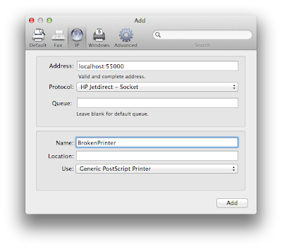
To install PDEs and PPDs navigate to: /Library/Printers/. The following steps may need authentication which is okay. Make a folder in /Library/Printers called Sample and dump the bundle you just compiled into the Sample folder. By default the downloaded example project will be placed in the Downloads folder. Next, the PPD needs to be installed. To install a PPD it first needs to be archived into a .gz folder. This may be done by first duplicating the PPD file. Rename the file to not have an extension i.e. OutputBinsPDETest. Open the terminal and navigate to downloaded project (cd ~/Downloads/OutputBinsPDE) and type gzip OutputBinsPDETest. Hit enter and notice that we now have a file named OutputBinsPDETest.gz. This file should be moved into the /Library/Printers/PPDs/Contents/Resources folder. Once this is complete we can now install a printer that uses this PPD/PDE combo by opening the System Preferences. At the add printer dialog click on the IP sub dialog. In the address go ahead and type localhost:55000 and select HP Jetdirect for the protocol. Leave the Queue field empty. See Figure 5 for a picture of the settings.
Figure 5: Printer Configuration 1

 Give the printer a name and under the Use menu select Select Printer Software, Figure 6. In the Filter type Bin and select Postscript Printer Manufacturer OutputBins PDE test. If a message such as the one shown in Figure 7 pops up, click Continue. Another dialog may pop up as shown in Figure 8, press Repair and wait because it may take a while. 
Figure 6: Printer Software Selection
Figure 7: Printer Software Configuration Warning 1

Figure 8: Printer Software Configuration Warning 2


Testing the PDE

Now we have the printer installed. Open TextEdit and print anything. Try to get to the advanced settings menu we just made, Figure 9. Oh no, the PDE is unsupported because it does not have a version for the current architecture Figure 10. Darn. 
Figure 9: Advanced Printer Settings

Figure 10: Unsupported PDE due to Architecture 

Go back to Xcode and go to the Build Settings, Figure 11. Change the Debug Architecture to Native Architecture of the Build Machine. This allows the PDE to be build for an x86_64 architecture. For a PDE to work it must match the architecture of the application which launched the print dialog. This become super hairy because some apps are build for i386 and some for x86_64, and if you are really unlucky one of the Power PC architectures. Keep that in mind if the PDE you develop is to be deployed. So now recompile and reinstall the PDE. You do not need to redo the part with the .gz file. To ensure the effects take hold quit TextEdit and force kill the printtool process in Activity Monitor. Now reprint something from TextEdit and try and navigate to the Output Bins menu, Figure 12 and 13. Cool, you now have a PDE.
Figure 11: Xcode Architectures Settings
Figure 12: Advanced Printer Settings

Figure 13: Advanced Printer Settings Panel

Thursday, February 16, 2012

BeagleBone GPIO Testing

Being completely new to embedded Linux and having only read how to use GPIO on other platforms I was quite pleased to finally get something working.


The script found here (1) was my starting place. The script seems extremely strait forward however I found myself struggling to figure out which GPIO # corresponded with which pin on the Beaglebone. Looking through the system reference manual for the BeagleBone and comparing it to the TI reference manual ended up confusing the issue. Basically the GPIO # corresponds to (32*First # + Second #) of a pin designation. To make this less confusing lets look at a couple of examples. First what is the pin number of GPIO0_15? Pluggin into the formula we get (32*0+15) therefore the pin number must be 15. How about one that is in the second GPIO bank, say GPIO2_23? Again, using the formula we get (32*2+23) which equals 87.

Another issue was TI reference manual states that the default mux setting for a pin corresponds to the pin name. So then I look at the BeagleBone manual and, for example, it says pin 25 on header J8 is GPIO1_0 you would think, Okay cool! I can export GPIO 32 (using the aforementioned formula) and blink an LED. Now if you try this without doing anything first you will end up with a LED that is dimly lit (at least that is what happened in my case, I am guessing a weak pull-up caused this behavior).

What could be wrong? Well it turns out whoever wrote the BeagleBone SRM (system reference manual)  decided that it would be awesome to rename all of the pins randomly to one of their many muxable outputs. Great.

How do we make it so we can we change these mux settings? First, we must first figure out what the acutal name of the pin is. This can be done by looking at what the primary mode of the pin is. In the case of pin 25 on header J8 we see that MODE0 is gpmc_ad0. Now that we have this information we can properly change the mux mode and other pin setting.


"The /sys/kernel/debug/omap_mux filenames are taken from the Mode 0 
usages of the pins, regardless of which mode the pin mux is currently 
in." - Found here (2)

Ok so if we want pin 25 on header J8 to actually be muxed to GPIO1_0 that means we need to set the mode to 7 (as per the BeagleBone SRM).

This command ought to do nicely:
echo 7 > /sys/kernel/debug/omap_mux/gpmc_ad0
To check an make sure the change was made properly you can run this:
cat /sys/kernel/debug/omap_mux/gpmc_ad0
which, if the pin was set correctly, should have this:
mode: OMAP_PIN_OUTPUT | OMAP_MUX_MODE7
as part of the output.

Sweet, we can now write something to toggle GPIO1_0 on pin 25 of header J8.

To recap here is what needs to be done in shell commands:
#Make sure the pin is in the right mode.
cat /sys/kernel/debug/omap_mux/gpmc_ad0
#If the mode returned by this command is not mux_mode7 set it.
echo 7 > /sys/kernel/debug/omap_mux/gpmc_ad0
#Okay now the pin is ready to be used
#Export the pin
echo 32 > /sys/class/gpio/export
#Turn the pin on
echo "high" > /sys/class/gpio/gpio32/direction
#Turn pin off
echo "low" > /sys/class/gpio/gpio32/direction
#Unexport the pin
echo 32 > /sys/class/gpio/unexport


Finally I want to leave links to the resources I used to figure this out.
(1) http://blog.makezine.com/2009/02/03/blinking-leds-with-the-beagle-board/
(2) https://groups.google.com/forum/?fromgroups#!topic/beagleboard/bPTTyClwn34
(3) http://beagleboard.org/static/beaglebone/a3/Docs/Hardware/BONE_SRM.pdf
(4) http://www.ti.com/product/am3359
For  (4) I used both the Technical Reference Manual and the AM335x ARM Cortex-A8 Microprocessors data sheets.